Introduction
This is an affordable, high quality, solar insolation sensor. The sensor is a Davis Weather 6450 solar radiation sensor with permanently attached interface electronics. The calibrated solar radiation sensor can measure 50 w/m^2 to 1800 w/m^2. The sensor comes standard with a 2 meter (6 foot) shielded cable with wire leads.
Photos of the sensor in action can be found in the Photo Gallery.

Solar insolation sensor, interface, & mounting hardware
Specifications
| Light Intensity | |
|---|---|
| Range: | 50 w/m^2 to 1800 w/m^2 |
| Accuracy: | ± 5% of full scale |
| Stability: | ± 2% per year |
| Transfer Function: | watts / m^2 = 598.802 * Vout |
| Input voltage: | 5.0 to 30 volts |
| Weight | |
| Weight: | ~175 g (6.2 oz) including 2 m (6 ft) shielded cable |
Pricing and Purchasing
Solar insolation sensor, integrated 2 m (6 ft) cable
Sensor and interface, mounting hardware hardware and integrated 2 m (6 ft) cable with bare wire ends.
Mounting Bracket
Solar insolation sensor mounting bracket
A mounting bracket specially designed for the solar insolation sensor.
Package Includes
- Mounting bracket - machined 6061-T6 aluminum
- 2 x clips - accommodate 12.7 mm (0.5 in) hose clamps for mounting to masts
- Set of screws and nuts for mounting on mast or solar panel

One of our customers leveling the solar insolation sensor.
Wind Data Logger Configuration
The insolation sensor is connected to the "TEMP&ADC" connector on the Wind Data Logger. You will need our RJ-45 Breakout Board to Screw Terminals to connect to our data loggers. The self contained data loggers have a breakout board built in.
To display actual sensor readings on the Wind Data Logger you will need to configure the ADC channels. The following equations are used to convert the voltage output from the sensors to standard units:
Light Intensity:
watts / meter^2=598.802*Vin (ADC M: 598.802 / ADC B: +0.0 / ADC Units: W)The values in parenthesis should be entered into the ADC setup screens on the Wind Data Logger.
Please Note: The pull-up resistor for the Solar Insolation Sensor's channel on the Wind Data Logger is removed when the sensor is ordered with the Wind Data Logger. If the sensor is ordered separately, please remove the resistor based on the connection below:
| Remove Connector: |
|---|
| R2 if connected to USER_ADC_0 (analog 4) |
| R3 if connected to USER_ADC_1 (analog 5) |
| R4 if connected to USER_ADC_2 (analog 6) |
| R19 if connected to USER_ADC_3 (analog 7) |
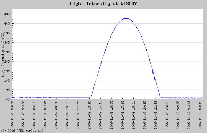
Example Data
The following data was captured on 2006-11-09 near Winona, Minnesota, USA.Solar Insolation


